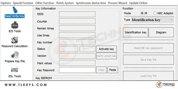
Xhorse VVDI MB BGA Tool Software Benz Key Programmer
Screenshots
Mercedes Benz Connection Diagram Gearbox ECU ELV ISM by VVDI MB
The connection diagram illustrates the interconnection of various components in Mercedes-Benz vehicles such as the Electronic Control Unit (ECU), Electronic Steering Lock (ELV), Integrated Signal Module (ISM), and Gearbox using the VVDI MB device.It depicts how these parts are linked, their electronic interactions, and the necessary wiring and communications for proper functioning.
This diagram can be invaluable to technicians and engineers involved in repairing and maintaining Mercedes-Benz cars, providing them with a comprehensive guide to the electronic connections of the mentioned components.
With VVDI MB, technicians can perform a variety of operations such as key programming, electronic system repairs, diagnostic troubleshooting, etc., which require a deep understanding of how devices and units are interconnected within the vehicle.
These images and diagrams can be important in learning and understanding the maintenance and repair processes for these complex electronic systems in Mercedes-Benz vehicles.
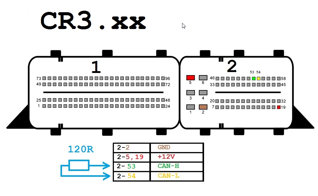
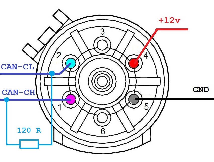
Connection Diagram ECU by VVDI MB
CR3-xx
Scheme components:
1: Power connector (12V)
2: CAN-CL line (green color)
3: CAN-CH line (yellow color)
4: Ground connector (GND)
5: K-line (purple color)
6: 120 ohm resistors (optional)
Basic ingredients:
Xhorse VVDI MB BGA Tool CR3.xx: Advanced programming tool to work on Mercedes Benz cars.
Engine Control Unit (ECU): An electronic control unit that operates a car's engine.
OBD-II Connector: A standard connector found on all OBD-II vehicles.
Cables: Special connection cables that connect the tool to the ECU.
Jobs:
Read PIN code:
VVDI MB BGA Tool CR3.xx allows you to read the PIN code of your vehicle's engine control unit (ECU) by connecting it to the OBD-II connector.
This PIN is used to program new keys to the vehicle.
Key programming:
VVDI MB BGA Tool CR3.xx allows you to program new keys for a vehicle using the PIN code or files taken from an existing key.
Various types of switches can be programmed, including BGA and NEC switches.
Other functions:
VVDI MB BGA Tool CR3.xx also supports other functions such as ECU reset, EIS, and ESL repair.
Delivery steps:
Connect the power connector (12V) to a suitable power outlet in the vehicle.
Connect the CAN-CL line (green color) to the CAN-CL connector on the ECU.
Connect the CAN-CH line (yellow color) to the CAN-CH connector on the ECU.
Connect the ground (GND) connector to any metal surface in the vehicle.
Connect the K-line (purple color) to the K-line connector on the ECU (optional).
Install 120 ohm resistors (optional) on the CAN-CL and CAN-CH lines.
Important notes:
Make sure to use the correct connectors and wires of the appropriate size.
Make sure all wires are connected securely before using the VVDI MB BGA Tool CR3.xx.
If you are not sure how to connect the VVDI MB BGA Tool CR3.xx, consult a professional technician.
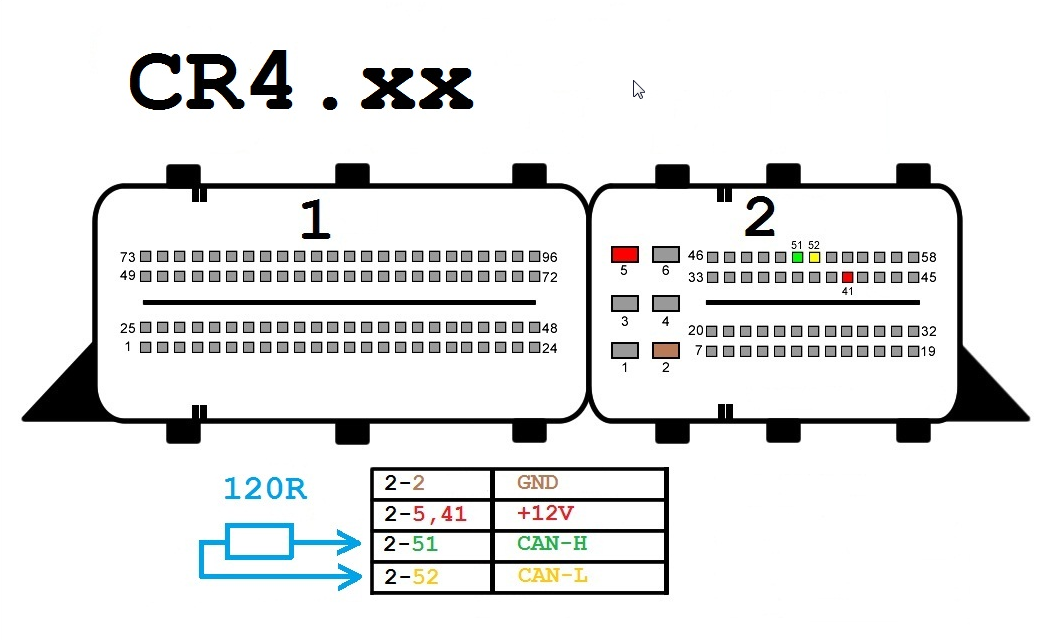
CR4-xx
Components:
- OBD-II Connector
- Xhorse VVDI MB BGA Tool CR4.xx
- 12 Volt Connector (Optional)
- 120 Ohm Resistors (Optional)
Wires:
- CAN-H (Yellow)
- CAN-L (Green)
- K-Line (Purple)
- GND (Black)
- +12V (Red)
Connection Steps:
- Connect the OBD-II connector to the VVDI MB BGA Tool CR4.xx.
- Connect the CAN-H wire to pin 6 on the OBD-II connector.
- Connect the CAN-L wire to pin 14 on the OBD-II connector.
- Connect the K-Line wire to pin 5 on the OBD-II connector.
- Connect the GND wire to pin 4 on the OBD-II connector.
- (Optional) Connect the +12V wire to pin 16 on the OBD-II connector.
- (Optional) Connect 120 Ohm resistors between the CAN-H and CAN-L wires.
Notes:
- Ensure all wires are correctly connected before using the VVDI MB BGA Tool CR4.xx.
- Connection steps may vary slightly depending on the specific car model and year of manufacture.
- Refer to the user manual of the VVDI MB BGA Tool CR4.xx for further detailed instructions.
Additional Information:
The VVDI MB BGA Tool CR4.xx can be used to perform various functions on Mercedes-Benz cars, including:
- Reading and removing PIN codes.
- Programming new keys for the car.
- Diagnosing ECU problems.
- Performing other maintenance and repair operations.
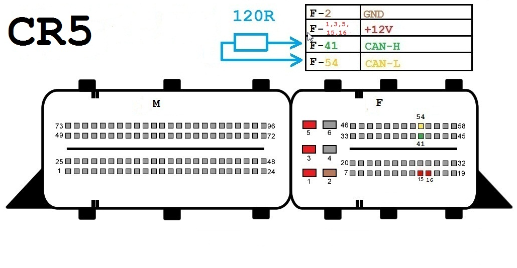
CR5
Components:
- OBD-II connector
- Xhorse VVDI MB BGA Tool CR5
- 12-volt connector (optional)
- 120-ohm resistors (optional)
Wires:
- CAN-H (Yellow)
- CAN-L (Green)
- K-Line (Purple)
- GND (Black)
- +12V (Red)
Connection Steps:
- Connect the OBD-II connector to the VVDI MB BGA Tool CR5.
- Connect the CAN-H wire to PIN 96 on the OBD-II connector.
- Connect the CAN-L wire to PIN 53 on the OBD-II connector.
- Connect the K-Line wire to PIN 54 on the OBD-II connector.
- Connect the GND wire to PIN 58 on the OBD-II connector.
- (Optional) Connect the +12V wire to PIN 45 on the OBD-II connector.
- (Optional) Connect the 120-ohm resistors between the CAN-H and CAN-L wires.
Notes:
- Ensure all wires are correctly connected before using the VVDI MB BGA Tool CR5.
- Connection steps may vary slightly depending on the car model and manufacturing year.
- Refer to the user manual of the VVDI MB BGA Tool CR5 for further detailed instructions.
Additional Information:
The VVDI MB BGA Tool CR5 can be used to perform various functions on Mercedes-Benz cars, including:
- Reading and removing PIN codes.
- Programming new keys for the car.
- Diagnosing ECU issues.
- Performing other maintenance and repair operations.
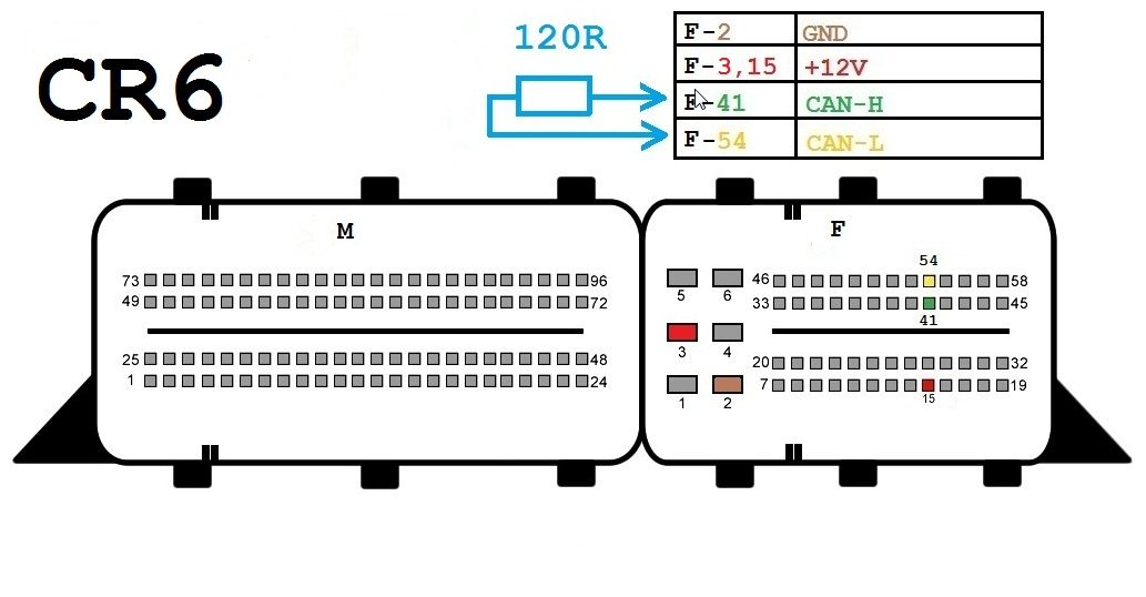
CR6
Components:
- OBD-II Connector
- Xhorse VVDI MB BGA Tool CR6
- 12V Connector (optional)
- 120-ohm Resistors (optional)
Wires:
- CAN-H (Yellow)
- CAN-L (Green)
- K-Line (Purple)
- GND (Black)
- +12V (Red)
Connection Steps:
- Connect the OBD-II connector to the VVDI MB BGA Tool CR6.
- Connect the CAN-H wire to pin 6 on the OBD-II connector.
- Connect the CAN-L wire to pin 14 on the OBD-II connector.
- Connect the K-Line wire to pin 5 on the OBD-II connector.
- Connect the GND wire to pin 4 on the OBD-II connector.
- (Optional) Connect the +12V wire to pin 16 on the OBD-II connector.
- (Optional) Connect the 120-ohm resistors between the CAN-H and CAN-L lines.
Notes:
- Ensure all wires are connected properly before using the VVDI MB BGA Tool CR6.
- Connection steps may vary slightly depending on the specific car model and year of manufacture.
- Please refer to the user manual of the VVDI MB BGA Tool CR6 for further detailed instructions.
Additional Information:
The VVDI MB BGA Tool CR6 can be used to perform various functions on Mercedes-Benz cars, including:
- Reading and removing PIN codes.
- Programming new keys for the car.
- Diagnosing ECU problems.
- Performing other maintenance and repair operations.
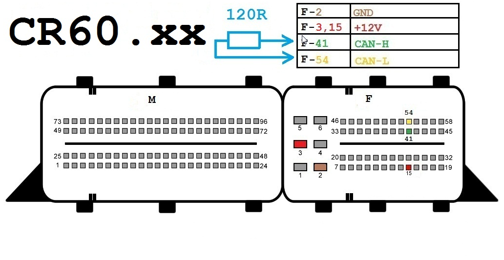
CR60-xx
Components:
- OBD-II Connector
- Xhorse VVDI MB BGA Tool CR60-xx
- 12 Volt Connector (Optional)
- 120-ohm Resistors (Optional)
Wires:
- CAN-H (Yellow)
- CAN-L (Green)
- K-Line (Purple)
- GND (Black)
- +12V (Red)
Connection Steps:
- Connect the OBD-II Connector to the VVDI MB BGA Tool CR60-xx.
- Connect the CAN-H wire to pin 6 on the OBD-II Connector.
- Connect the CAN-L wire to pin 14 on the OBD-II Connector.
- Connect the K-Line wire to pin 5 on the OBD-II Connector.
- Connect the GND wire to pin 4 on the OBD-II Connector.
- (Optional) Connect the +12V wire to pin 16 on the OBD-II Connector.
- (Optional) Connect 120-ohm resistors between the CAN-H and CAN-L wires.
Important Notes:
- Ensure all wires are properly connected before using the VVDI MB BGA Tool CR60-xx.
- Connection steps may vary slightly depending on the car model and manufacturing year.
- Refer to the user manual of the VVDI MB BGA Tool CR60-xx for further detailed instructions.
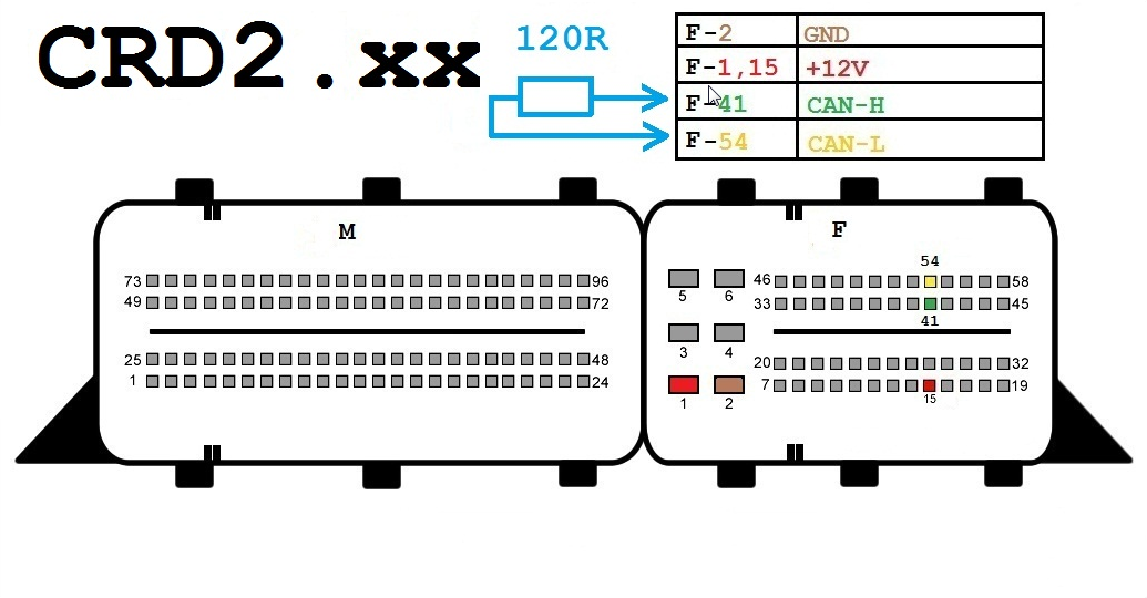
CRD2-xx
Components:
- OBD-II connector
- Xhorse VVDI MB BGA Tool CRD2-xx
- 12-volt connector (optional)
- 120-ohm resistors (optional)
Wiring:
- CAN-H (Yellow)
- CAN-L (Green)
- K-Line (Purple)
- GND (Black)
- +12V (Red)
Connection Steps:
- Connect the OBD-II connector to the VVDI MB BGA Tool CRD2-xx.
- Connect the CAN-H wire to pin 96 on the OBD-II connector.
- Connect the CAN-L wire to pin 53 on the OBD-II connector.
- Connect the K-Line wire to pin 54 on the OBD-II connector.
- Connect the GND wire to pin 58 on the OBD-II connector.
- (Optional) Connect the +12V wire to pin 45 on the OBD-II connector.
- (Optional) Connect 120-ohm resistors between the CAN-H and CAN-L lines.
Notes:
- Ensure all wires are connected correctly before using the VVDI MB BGA Tool CRD2-xx.
- Connection steps may vary slightly depending on the specific car model and year of manufacture.
- Refer to the user manual of the VVDI MB BGA Tool CRD2-xx for more detailed instructions.
Additional Information:
The VVDI MB BGA Tool CRD2-xx can be used to perform various functions on Mercedes-Benz cars, including:
- Reading and removing PIN codes.
- Programming new keys for the car.
- Diagnosing ECU issues.
- Performing other maintenance and repair operations.
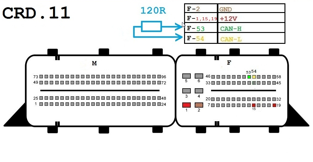
CRD-11
Components:
- OBD-II Connector
- Xhorse VVDI MB BGA Tool CRD-11
- 12V Connector (Optional)
- 120-ohm Resistors (Optional)
Wires:
- CAN-H (Yellow)
- CAN-L (Green)
- K-Line (Purple)
- GND (Black)
- +12V (Red)
Connection Steps:
- Connect the OBD-II Connector to the VVDI MB BGA Tool CRD-11.
- Connect the CAN-H wire to Pin 6 on the OBD-II Connector.
- Connect the CAN-L wire to Pin 14 on the OBD-II Connector.
- Connect the K-Line wire to Pin 5 on the OBD-II Connector.
- Connect the GND wire to Pin 4 on the OBD-II Connector.
- (Optional) Connect the +12V wire to Pin 16 on the OBD-II Connector.
- (Optional) Connect 120-ohm Resistors between CAN-H and CAN-L lines.
Notes:
- Ensure all wires are connected properly before using the VVDI MB BGA Tool CRD-11.
- Connection steps may vary slightly depending on the specific car model and manufacturing year.
- Refer to the user manual of the VVDI MB BGA Tool CRD-11 for further detailed instructions.
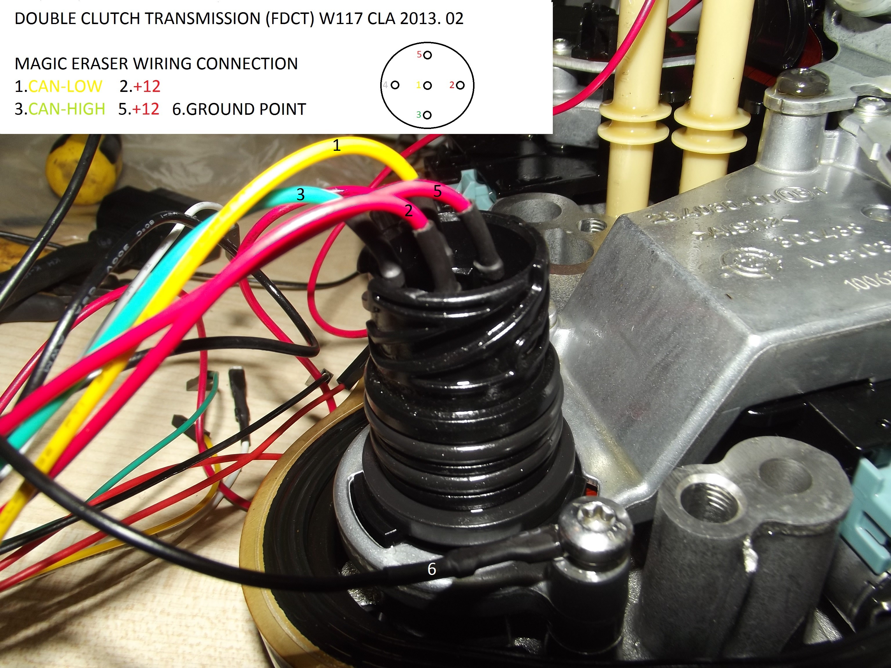
FDCT
Components:
- OBD-II connector
- Xhorse VVDI MB BGA Tool FDCT
- 12-volt connector (optional)
- 120-ohm resistors (optional)
Wires:
- CAN-H (yellow)
- CAN-L (green)
- K-Line (purple)
- GND (black)
- +12V (red)
Connection Steps:
- Connect the OBD-II connector to the VVDI MB BGA Tool FDCT.
- Connect the CAN-H wire to pin 6 on the OBD-II connector.
- Connect the CAN-L wire to pin 14 on the OBD-II connector.
- Connect the K-Line wire to pin 5 on the OBD-II connector.
- Connect the GND wire to pin 4 on the OBD-II connector.
- (Optional) Connect the +12V wire to pin 16 on the OBD-II connector.
- (Optional) Connect 120-ohm resistors between the CAN-H and CAN-L lines.
Notes:
- Ensure all wires are properly connected before using the VVDI MB BGA Tool FDCT.
- Connection steps may vary slightly depending on the specific car model and year of manufacture.
- Please refer to the user manual of the VVDI MB BGA Tool FDCT for further detailed instructions.
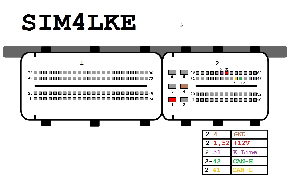
SIM4LKE
Components:
- OBD-II connector
- Xhorse VVDI MB BGA Tool SIM4LKE
- 12-volt connector (optional)
- 120-ohm resistors (optional)
Wires:
- CAN-H (Yellow)
- CAN-L (Green)
- K-Line (Purple)
- GND (Black)
- +12V (Red)
Connection Steps:
- Connect the OBD-II connector to the VVDI MB BGA Tool SIM4LKE.
- Connect the CAN-H wire to PIN 96 on the OBD-II connector.
- Connect the CAN-L wire to PIN 53 on the OBD-II connector.
- Connect the K-Line wire to PIN 54 on the OBD-II connector.
- Connect the GND wire to PIN 58 on the OBD-II connector.
- (Optional) Connect the +12V wire to PIN 45 on the OBD-II connector.
- (Optional) Connect the 120-ohm resistors between the CAN-H and CAN-L lines.
Important Notes:
- Ensure all wires are correctly connected before using the VVDI MB BGA Tool SIM4LKE.
- Connection steps may vary slightly depending on the specific car model and manufacturing year.
- Please refer to the user manual of the VVDI MB BGA Tool SIM4LKE for further detailed instructions.
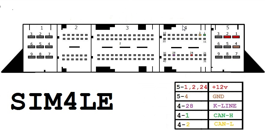
SIM4LE
Components:
- OBD-II connector
- Xhorse VVDI MB BGA Tool SIM4LE
- 12-volt connector (optional)
- 120-ohm resistors (optional)
Wires:
- CAN-H (Yellow)
- CAN-L (Green)
- K-Line (Purple)
- GND (Black)
- +12V (Red)
Connection Steps:
- Connect the OBD-II connector to the VVDI MB BGA Tool SIM4LE.
- Connect the CAN-H wire to pin 1 on the OBD-II connector.
- Connect the CAN-L wire to pin 2 on the OBD-II connector.
- Connect the K-Line wire to pin 24 on the OBD-II connector.
- Connect the GND wire to pin 5 on the OBD-II connector.
- (Optional) Connect the +12V wire to pin 28 on the OBD-II connector.
- (Optional) Connect 120-ohm resistors between the CAN-H and CAN-L lines.
Notes:
- Ensure all wires are correctly connected before using the VVDI MB BGA Tool SIM4LE.
- Connection steps may vary slightly depending on the specific car model and manufacturing year.
- Refer to the user manual of the VVDI MB BGA Tool SIM4LE for further detailed instructions.
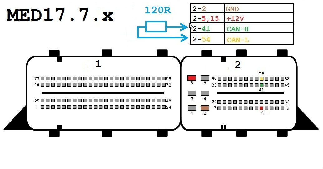
MED17-7-x
Components:
- OBD-II Connector
- Xhorse VVDI MB BGA Tool MED17-7-x
- 12-Volt Connector (Optional)
- 120-ohm Resistors (Optional)
Wiring:
- CAN-H (Yellow)
- CAN-L (Green)
- K-Line (Purple)
- GND (Black)
- +12V (Red)
Connection Steps:
- Connect the OBD-II Connector to the VVDI MB BGA Tool MED17-7-x.
- Connect the CAN-H wire to Pin 6 on the OBD-II Connector.
- Connect the CAN-L wire to Pin 14 on the OBD-II Connector.
- Connect the K-Line wire to Pin 5 on the OBD-II Connector.
- Connect the GND wire to Pin 4 on the OBD-II Connector.
- (Optional) Connect the +12V wire to Pin 16 on the OBD-II Connector.
- (Optional) Connect 120-ohm Resistors between the CAN-H and CAN-L lines.
Notes:
- Ensure all wires are properly connected before using the VVDI MB BGA Tool MED17-7-x.
- Connection steps may vary slightly depending on the specific car model and manufacturing year.
- Please refer to the user manual of the VVDI MB BGA Tool MED17-7-x for further detailed instructions.
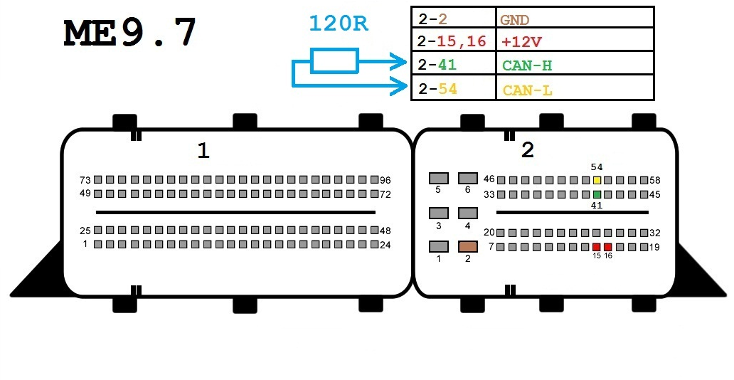
ME9-7
Components:
- OBD-II connector
- Xhorse VVDI MB BGA Tool ME9-7
- 12-volt connector (optional)
- 120-ohm resistors (optional)
Wires:
- CAN-H (Yellow)
- CAN-L (Green)
- K-Line (Purple)
- GND (Black)
- +12V (Red)
Connection Steps:
- Connect the OBD-II connector to the VVDI MB BGA Tool ME9-7.
- Connect the CAN-H wire to pin 6 on the OBD-II connector.
- Connect the CAN-L wire to pin 14 on the OBD-II connector.
- Connect the K-Line wire to pin 5 on the OBD-II connector.
- Connect the GND wire to pin 4 on the OBD-II connector.
- (Optional) Connect the +12V wire to pin 16 on the OBD-II connector.
- (Optional) Connect 120-ohm resistors between the CAN-H and CAN-L lines.
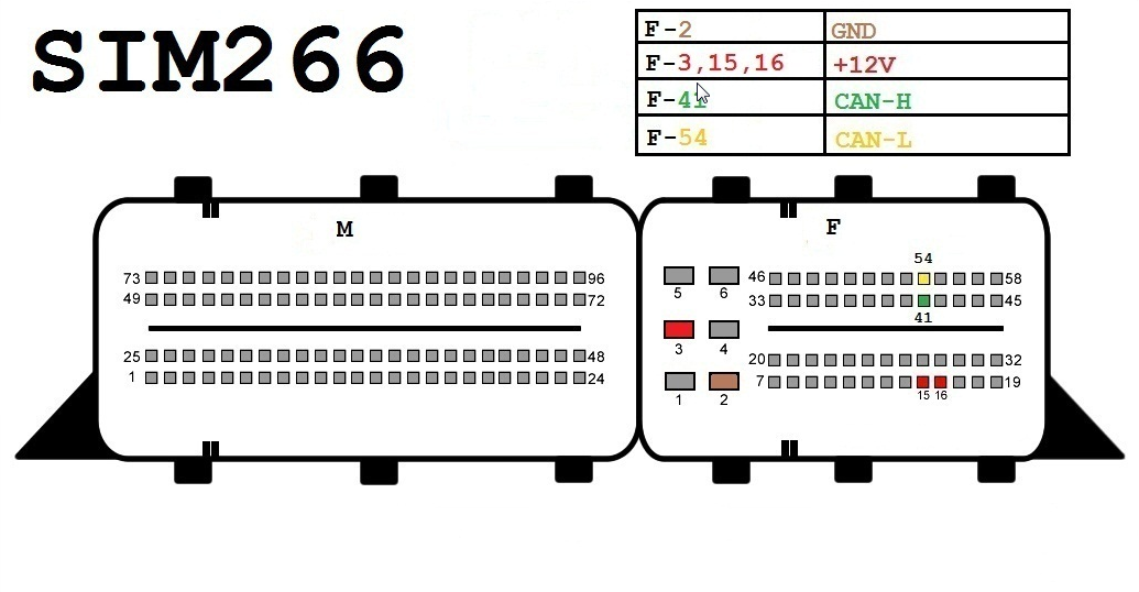
SIM266
Components:
- OBD-II connector
- Xhorse VVDI MB BGA Tool ME9-7
- 12-volt connector (optional)
- 120-ohm resistors (optional)
Wires:
- CAN-H (Yellow)
- CAN-L (Green)
- K-Line (Purple)
- GND (Black)
- +12V (Red)
Connection Steps:
- Connect the OBD-II connector to the Xhorse VVDI MB BGA Tool ME9-7.
- Connect the CAN-H wire to PIN 6 on the OBD-II connector.
- Connect the CAN-L wire to PIN 14 on the OBD-II connector.
- Connect the K-Line wire to PIN 5 on the OBD-II connector.
- Connect the GND wire to PIN 4 on the OBD-II connector.
- (Optional) Connect the +12V wire to PIN 16 on the OBD-II connector.
- (Optional) Connect 120-ohm resistors between the CAN-H and CAN-L lines.
Important Notes:
- Ensure all wires are correctly connected before using the Xhorse VVDI MB BGA Tool ME9-7.
- Connection steps may vary slightly depending on the specific car model and year of manufacture.
- Refer to the user manual of the Xhorse VVDI MB BGA Tool ME9-7 for further detailed instructions.
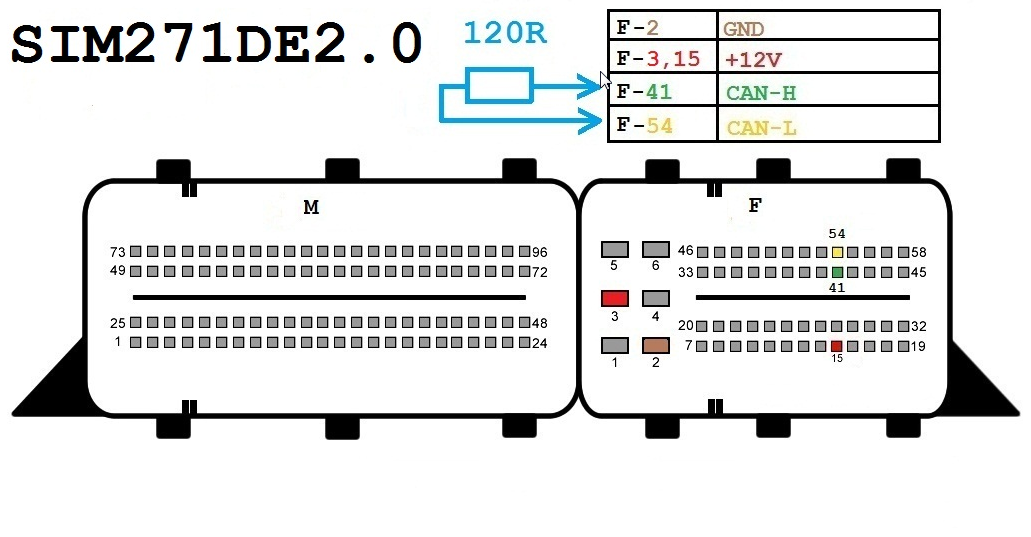
SIM271DE2-0
Components:
- OBD-II connector
- Xhorse VVDI MB BGA Tool SIM271DE2-0
- 12-volt connector (optional)
- 120-ohm resistors (optional)
Wiring:
- CAN-H (Yellow)
- CAN-L (Green)
- K-Line (Purple)
- GND (Black)
- +12V (Red)
Connection Steps:
- Connect the OBD-II connector to the VVDI MB BGA Tool SIM271DE2-0.
- Connect the CAN-H wire to PIN 41 on the OBD-II connector.
- Connect the CAN-L wire to PIN 54 on the OBD-II connector.
- Connect the K-Line wire to PIN 72 on the OBD-II connector.
- Connect the GND wire to PIN 1 on the OBD-II connector.
- (Optional) Connect the +12V wire to PIN 24 on the OBD-II connector.
- (Optional) Connect 120-ohm resistors between the CAN-H and CAN-L lines.
Notes:
- Ensure all wires are correctly connected before using the VVDI MB BGA Tool SIM271DE2-0.
- Connection steps may vary slightly depending on the specific car model and year of manufacture.
- Please refer to the user manual of the VVDI MB BGA Tool SIM271DE2-0 for further detailed instructions.
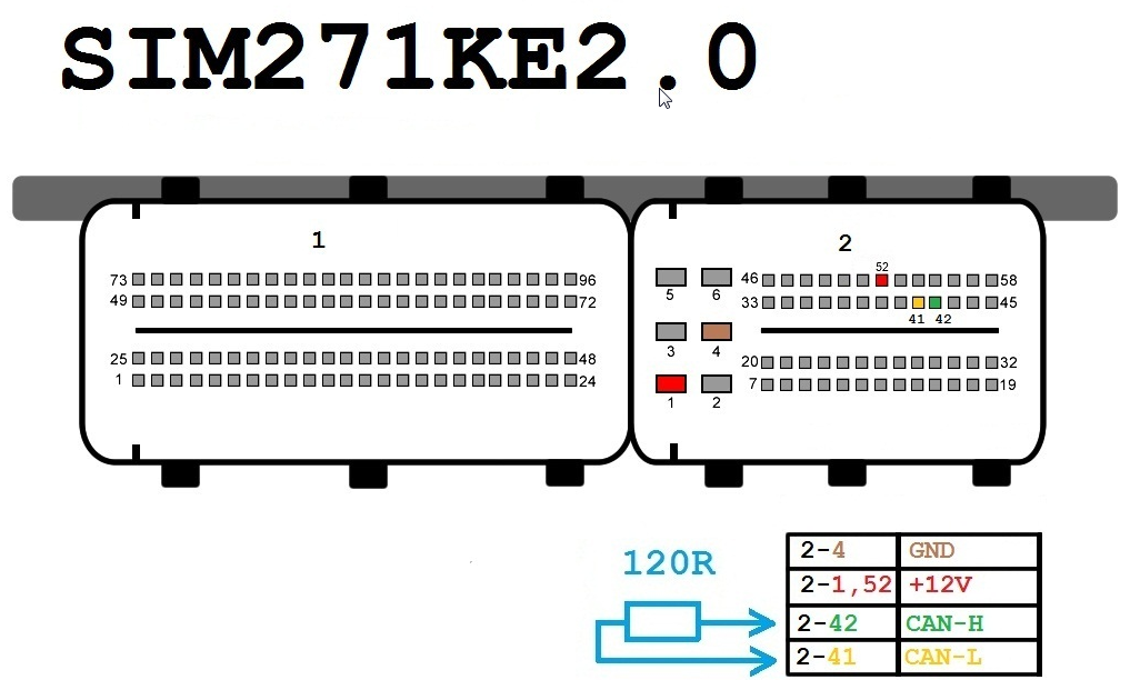
SIM271KE2-0
Components:
- OBD-II connector
- Xhorse VVDI MB BGA Tool SIM271KE2-0
- 12-volt connector (optional)
- 120-ohm resistors (optional)
Wires:
- CAN-H (Yellow)
- CAN-L (Green)
- K-Line (Purple)
- GND (Black)
- +12V (Red)
Connection Steps:
- Connect the OBD-II connector to the Xhorse VVDI MB BGA Tool SIM271KE2-0.
- Connect the CAN-H wire to pin 41 on the OBD-II connector.
- Connect the CAN-L wire to pin 54 on the OBD-II connector.
- Connect the K-Line wire to pin 72 on the OBD-II connector.
- Connect the GND wire to pin 1 on the OBD-II connector.
- (Optional) Connect the +12V wire to pin 24 on the OBD-II connector.
- (Optional) Connect the 120-ohm resistors between the CAN-H and CAN-L lines.
Notes:
- Ensure all wires are correctly connected before using the Xhorse VVDI MB BGA Tool SIM271KE2-0.
- Connection steps may vary slightly depending on the specific car model and year of manufacture.
- Please refer to the user manual of the Xhorse VVDI MB BGA Tool SIM271KE2-0 for further detailed instructions.
Gearbox
Components:
- Special connector for gearbox
- Xhorse VVDI MB BGA Tool
Wires:
- +12 volts (Red)
- GND (Black)
- K-Line (Purple, optional)
Connection Steps:
- Identify the location of the gearbox connector in your car. Refer to the car's user manual or online sources for assistance in identifying its location.
- Connect the special connector for the gearbox to the Xhorse VVDI MB BGA Tool.
- Connect the +12-volt wire to the red terminal on the gearbox connector.
- Connect the GND wire to the black terminal on the gearbox connector.
- (Optional) Connect the K-Line wire to the purple terminal on the gearbox connector. K-Line may not be required depending on the car or procedure being performed.
ISM
Components
- Special connector for ISM unit
- Xhorse VVDI MB BGA Tool
- 12-volt DC power source (optional)
- 120-ohm resistors (optional)
Wires
- CAN-H (Yellow)
- CAN-L (Green)
- +12 Volts (Red)
- GND (Black)
Connection Steps
- Locate the ISM unit connector in your car. Refer to the car's user manual or online sources for assistance in locating it.
- Connect the ISM unit connector to the Xhorse VVDI MB BGA Tool.
- Connect the CAN-H wire to the yellow terminal on the ISM unit connector.
- Connect the CAN-L wire to the green terminal on the ISM unit connector.
- (Optional) Connect the +12 Volts wire to the red terminal on the ISM unit connector.
- Connect the GND wire to the black terminal on the ISM unit connector.
- (Optional) Connect 120-ohm resistors between the CAN-H and CAN-L lines if your power source does not already provide termination resistance.
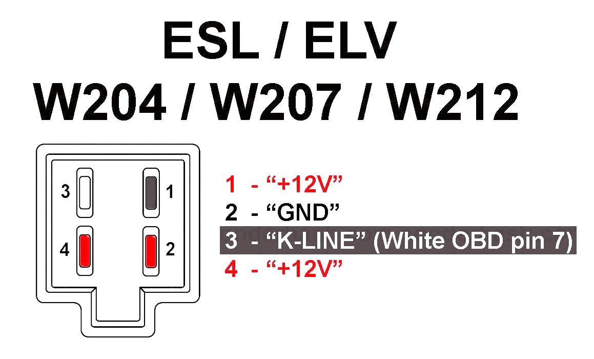
Steering Lock ELV W204
Components
- Special connector for ISM unit
- Xhorse VVDI MB BGA Tool
- 12-volt DC power source (optional)
- 120-ohm resistors (optional)
Wires
- CAN-H (Yellow)
- CAN-L (Green)
- +12V (Red)
- GND (Black)
Connection Steps
- Identify the location of the ISM unit connector in your car. Refer to the car's user manual or online sources to assist in locating it.
- Connect the ISM unit connector to the Xhorse VVDI MB BGA Tool.
- Connect the CAN-H wire to the yellow terminal on the ISM unit connector.
- Connect the CAN-L wire to the green terminal on the ISM unit connector.
- (Optional) Connect the +12V wire to the red terminal on the ISM unit connector.
- Connect the GND wire to the black terminal on the ISM unit connector.
- (Optional) Connect 120-ohm resistors between the CAN-H and CAN-L lines if your power source does not already provide resistor termination.