Page 1 of 3
SKU: TL32056
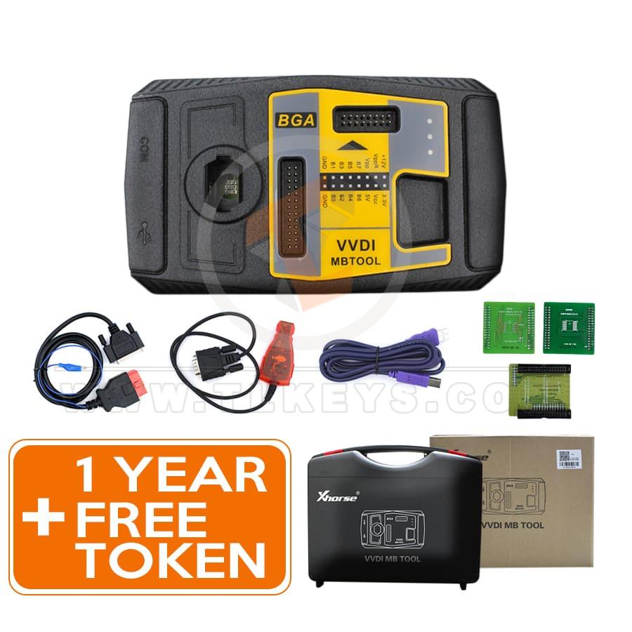
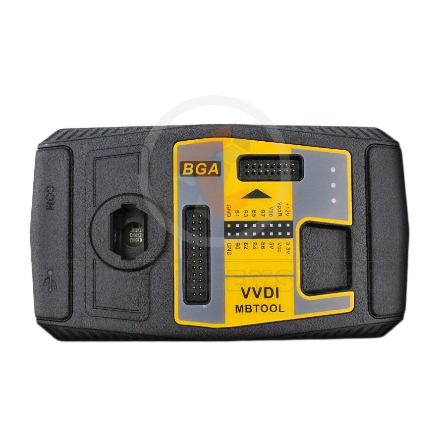
Xhorse VVDI MB BGA Tool Mercedes Benz Key Programmer Plus 1 Year Free Token
$890.00
- SKU: TL32056
-
Category:
Key Programming - Diagnostics Tools
- MANUFACTURER: Xhorse
Attributes
| weight | 2 KG |
|---|
Models
| Brand | Model | From | To |
|---|---|---|---|
| Mercedes Benz | All | all | all |
Videos
Xhorse XDMBC0EN VVDI MB BGA Tool Benz Key Programmer Support 1997-2014 FBS3 + one-year unlimited tokens
Frequent updates for more and more functions.Now supports all key lost: W210, w204, w207, W166, W246, W212, W212 (old), W230, some W216, W164 2009-, W164/W251 2004-2008 and some others.
They are mainly used for key reading and writing, EIS tools, password calculation, key file preparation, ESL tools, ECU/Gearbox renewal, and many functions specials.
It will allow you to program new keys to your customer's Mercedes without the need for soldering/desoldering.
Support Mercedes Benz keys read passwords, and prepare new keys via IR

VVDIMB Update Log:
Latest version V5.1.6(2023-06-12)
Require firmware V5.0.1
1. Bugfix


Xhorse VVDI MB BGA Tool General features:
1. Support BE key, read password, and prepare new key via IR.2. All NEC keys support built-in writing and erasing
Support NEC V051, V057 on board get password
3. Password Calculation: Read EIS in OBD mode will automatically check car power.
Avoid data loss in EIS
Support BGA keys, NEC keys (including 51.57 version), etc., and work fast.
4. Support the Renewal of EIS and ELV
5. Support EIS and ELV Writing
6. Support Online Generation of Key File
7. Unlock the ELV function
8. Renew other control modules functions will support soon
9. Free Update Lifetime

VVDI MB Tool Latest Version Software V5.1.5 Free Download
VVDI MB TOOL V5.1.6 Download SoftwareVVDI MB TOOL Download Driver
VVDI MB Highlights :
- Latest Software Version: V5.1.6, Requires firmware V5.1.6
- Multi-language: English, Polish, Spanish, Chinese
- It supports a password calculation function.
VVDI MB requires 1 token (2 tokens for all keys lost).
Other functions are free to use. - Combine VVDI MB with a condor or dolphin automatic key-cutting machine.
- If you have CONDOR XC-002, you can also get 1 free token daily.
If you have both XC002 and Condor mini or Dolphin machines, your VVDI MB can have up to 2 free tokens per day.
(NOTE Dolphin XP007 cannot be combined with VVDI MB to get a free token) - Support all key lost: W166, W197, W212, W218, W246, W206, W210, W204, W207, W166, W203, W463, W639, W246, W212, W212 (old), some W216, W164 2009 -, W164, W221, W215, W220, W230, W164/ W251 04-08 and some others.
- Support FBS4 disable key function (other function-> FBS4 disable key) - Support W166 W205 W213 W218 W222 W246 type
- Frequent online updates


Xhorse VVDI MB Tool Function :
1. Read and write key
Identification key, read and write IR BE key.Red version V51, V57 key password by NEC adapter.
Read activate blank BGA(OCF4) key.
current key Hash (repair).
Renew, write to used NEC key.
Write smart key etc.
2. Password Calculation
OBD reads and calculates all (FBS3) can protocol the EIS password.Support password calculation of BGA Key, NEC Key, V51, and V57 versions.
Support all key lost W164, W216, W166, W211, W212, W246, W212 (OLD), W204, W207 ECT.
online calculation key password, fast work.
3. ESL TOOLS
OBD (K line) read data, renew ESL, replace ESL (no need to renew EIS).check ESL damage, repair W204 ESL


4. Read/Write Gateway
Support OBD KM repair: W204, W207, W211, W251, W154, W212, W221, W216, W166, W172, W232, W205, etc.Support EEPROM and Flash read and write gateway: W211, W164, W204, W207, W212, W221, W216, etc.
5. EIS Tools
Read and write EIS by OBD or IR, OBD auto-detect, access to W164, W209, and W211 without gateway.Read the password from the old Motorola EIS (K-Line).
Renew EIS, replace EIS, activate the key, deactivate key, customize W204 ESL.
Test EIS status, working key, etc.
6. Prepare the Key File
Online generation of the key file for versions V11, V41, and V51.Support Motorola EIS EEPROM file, with high efficiency, 100% generate successfully
7. Program or Renew ECU/Gearbox/ISM
Features include support renewal, writing VIN, customizing operation for ECU module, gearbox, ISM, etc.8. Unlock the ELV function

9. Renew the function of another control module
10. CGW (ZGW) Read/Write, KM Repair
Support repair of the following KM: W204, W207, W212, W251, W164, W211, W221, W216, W166, Wl72, W232 and W205 etc.Support read/write gateway EEPROM and FLASH: W211/W164, W204/W207/W212, W221 and W216 etc.
IR/OBD Model Support:
W164, W164 2009+A166, W197, W212, W218, A246
A169, W209, W211
W172, W204, A207
W203
W204, W207, W212 only by dump
NEW!—W204, W207 via ALL KEYS LOST infrared option
W209 only by dump
W210
W215, W220
W230
W216
W221
W906

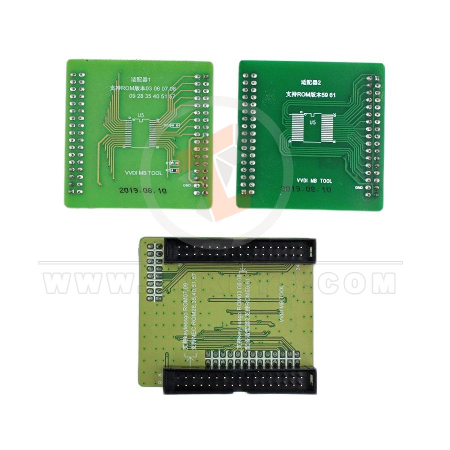
Supported key version:
v03,v06,v08v05,v07,v09
v59, v61
What keys/remotes are supported?
705 Motorcycle 1997-2000NEC 2001-2005
NEC 2006-2010
BGA 2011+
VVDI Mercedes has a new quick password calculation for all keys lost which can be done in less than 15 minutes
Xhorse VVDI MB software currently supports the following models:
W216 all key lost fast password calculation
W164 all keys lost fast password calculation
W251 all keys lost fast password calculation
W169 all key lost fast password calculation
W209 all key lost fast password calculation
W211 all key lost fast password calculation
W202 all key lost fast password calculation
W208 all key lost fast password calculation
W210 all key lost fast password calculation
W203 all key lost fast password calculation
W463 all keys lost fast password calculation
W639 all key lost fast password calculation
W215 all key lost fast password calculation
W220 all key lost fast password calculation
W639 2009 - all keys lost fast password calculation
W906 all key lost fast password calculation
W221 all key lost fast password calculation
W230 all key lost fast password calculation
Note: A special gateway is required for this procedure.


Xhorse VVDI MB Tokens:
1. For W166, W212, W246, W212 (old), W204, W207, W216, W164 2009-all keys are lost, need two tokens when calculation succeeds
2. For W164, W164 2009-, W166, 197, 212, 218, 246, W169, 209, 211, W172, 204, 207, 212 (old), W216, W221, W639 2009-
add key, token/each calculation.
3 Ways to Get VVDI MB Tokens:
1. buy tokens for the amount you want2. buy unlimited VVDI MB tokens for one year of use
3. Free
Redeem bonus points for tokens, if you own an Xhorse key machine like
Condor XC Mini
Condor XC Mini Plus
Dolphin Condor
Xhorse will give you one free token per day.
Tokens are needed when calculating a key password (internet connection required).
All Keys Lost: 2 tokens required
Add new key with spare key: 1 token required
All other online calculations are free and do not require the use of a token.
How to update VVDI MB Tool software and firmware?
Update VVDI Benz SoftwareThis feature requires internet support
Use " Menu -> Online Update -> Software Update" to get the latest software version of VVDI-MB TOOL, the software version requires firmware version, etc.
Tap the download link to download the latest software version.
If there is no display for the software version, close your firewall and anti-virus programs, and try again.
Firmware Update Steps:
1) Connect VVDI - MB TOOL to PC with a USB cable
2) Choose the VVDI - MB TOOL firmware version from the firmware list
3) Press the Update Online button, and wait for the progress to finish
4) If you are unable to get a firmware list or get something like " an error communicating with the server!"
While updating your device, close the anti-virus and firewall programs and try again.
Changing ISP once again failed.
5) Do NOT turn off your PC or unplug the USB cable while the device is updating
How to combine VVDI Mercedes Benz and VVDI2 in the Xhorse app?
Run the upgrade kit, connect the device to the PC by USB cable, and read the device.
Select ' Binding' and the customer will receive a QR code automatically.
Log into Xhorse APP, enter 'Account'--'Combine Device'.
Then scan the QR code to combine to the account.
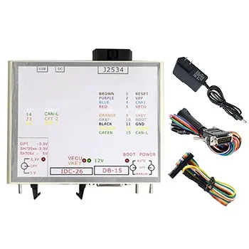
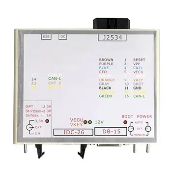
VVDI MB Optional Adapter:
Power Adapter Work With W164 W204 Data AcquisitionTesting Cables For Benz Gateway 210 208 202
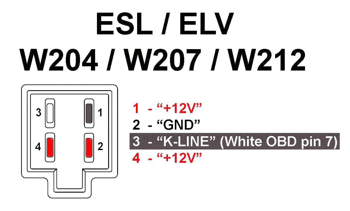
EIS ELV Test Line For Mercedes
EIS ELV Test Line For Mercedes 7-G Cable
IR Reader For Benz
EIS ELV Test Line For Mercedes ISM Cable
NEC Key Socket Adapter XDMB09
XDMB02EN VVDI MB Tool Key Programmer OBD Cable
VVDI MB BGA Xhorse FAQs
1. Q: I tested read data with OBD 210K line working and car 204 read with OBD2, but 211 was not read with OBD2 cable connection16 12v
4+5GND
14 CAN_L
6 CAN_H
pin 1: ESL 1
pin 2: GND
pin 3: +12V (30)
Pin 5: CAN L (White)
Pin 6: CAN H (Green)
pin 7: CAN L
pin 8: CAN H
CAN ANYBODY TEST
A: Read EIS via OBD for W164, W169, W211, W209, need gateway connected
2. Q: I purchased an EIS W221 lock with a key from a machine lock. I read the PSW. I will make a complete loss of the W221 key in the future.
Describe the procedure step by step
A: You used/Second-hand EIS with a working key, you can do this for W221 all keys lost
1. Read all key lost EIS data -> Save EIS data
2. Read used EIS data, enter the password, clear the password -> renew the used EIS.
3. Load EIS data from step 1 into renewed EIS with password -> write EIS data
4.load EIS data(with key password)->prepare key file
5. Enter new key in device IR reader-> load key file-> write
6. insert new key in EIS-> EIS will learn new key-> key learning success
By the way, if your key lost W221 is Motorola EIS, no need to change EIS, delete EIS, and get EEPROM by a programmer (VVDI PROG).
then load EEPROM into VVDI MB TOOL and prepare the key file.
3. Q: I lost a W204 All key and I programmed a new EIS with VVDI, the ignition won't turn on or start, but the steering can lock and unlock.
Can anyone guide me on what to do?
A: About W204, all keys are lost new EIS), refer to the following steps, which may be helpful:
1. Read EIS data via OBD, then save EIS data
2. Adapt ESL: Read ESL Data-> Get Erase Password-> Renew ESL
3. Change new EIS, load EIS data (step 1)-> write key password (enter manually and randomly)-> write EIS data
4. Customize W204 ESL
5. Load EIS data (with key password)-> Prepare key file
6. Enter new key in device IR reader-> Load key file-> write
7. Insert new key in EIS-> EIS will learn new key-> key learning success
4. Q: Is there any way to delete the key used with VVDI MB BGA?
A: Yes, VVDI MB TOOL supports that!

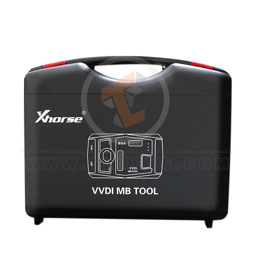
Xhorse VVDI MB BGA Package List:
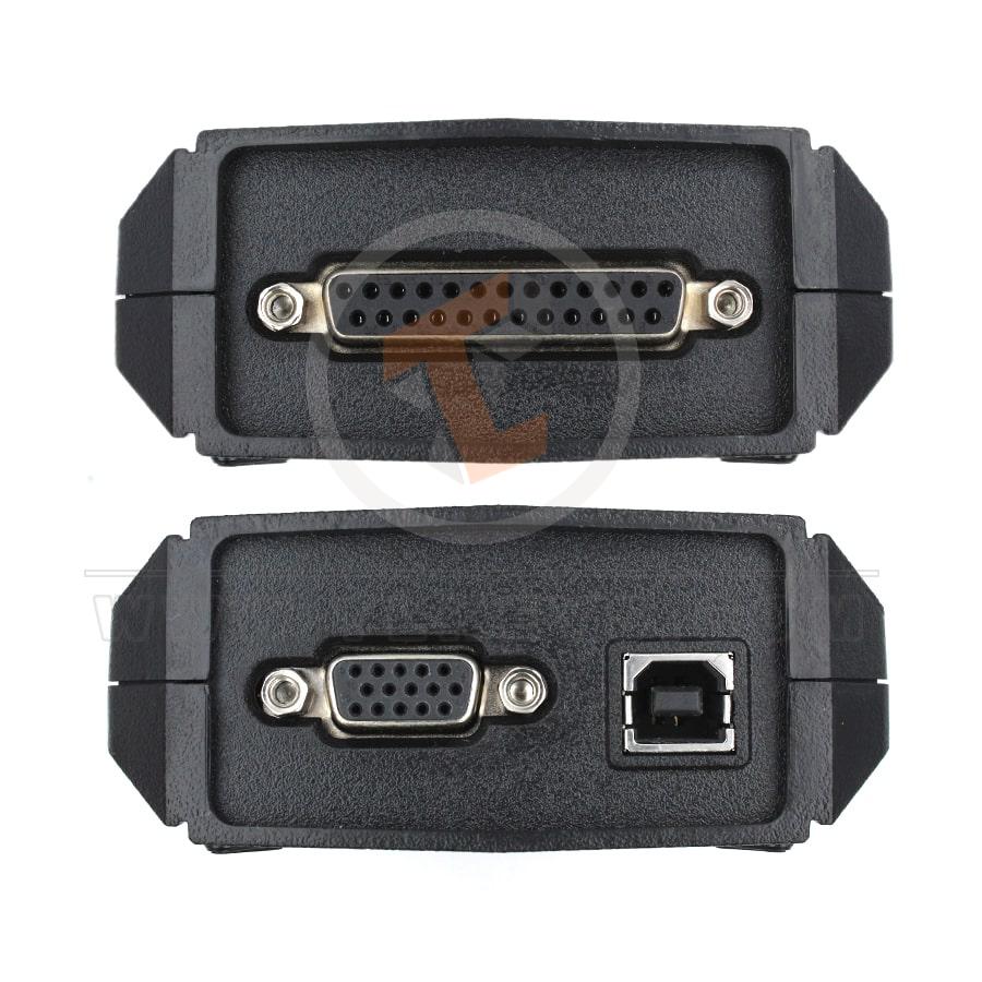
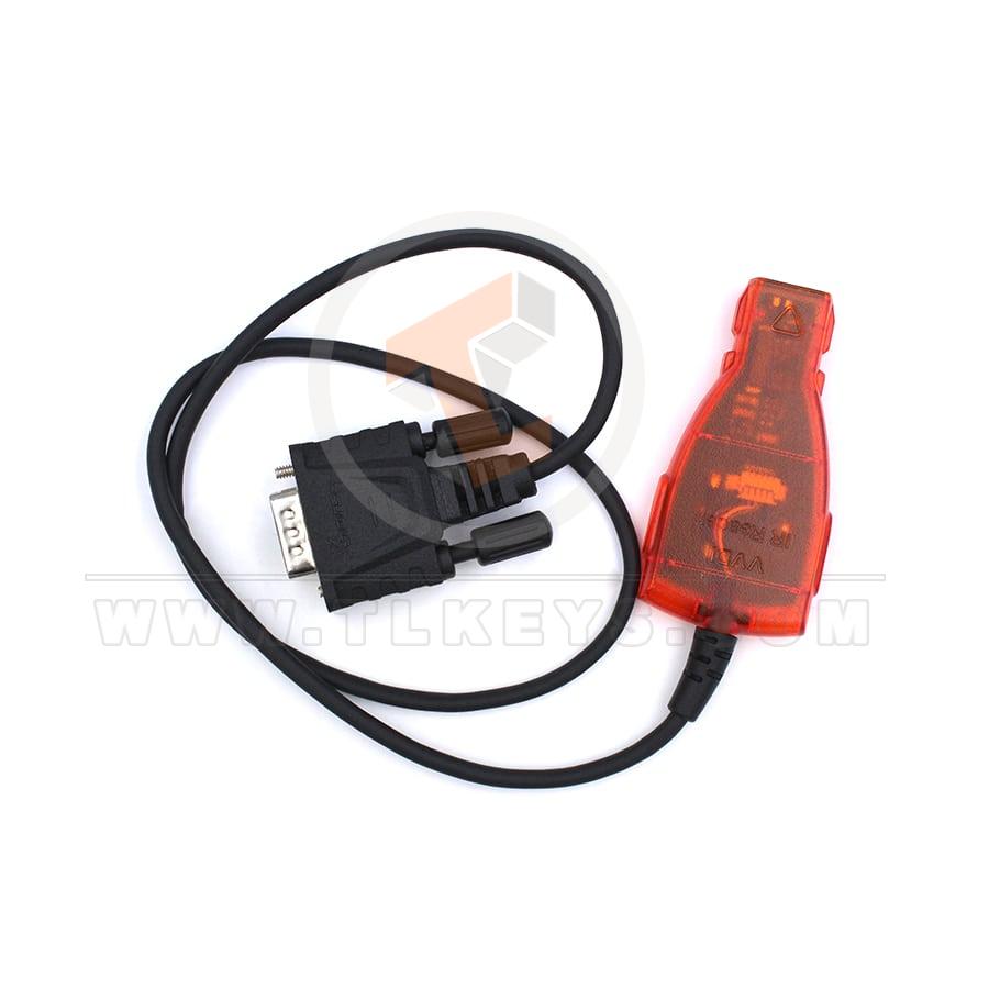
1. VVDI-MB TOOL device2. IR Adapter
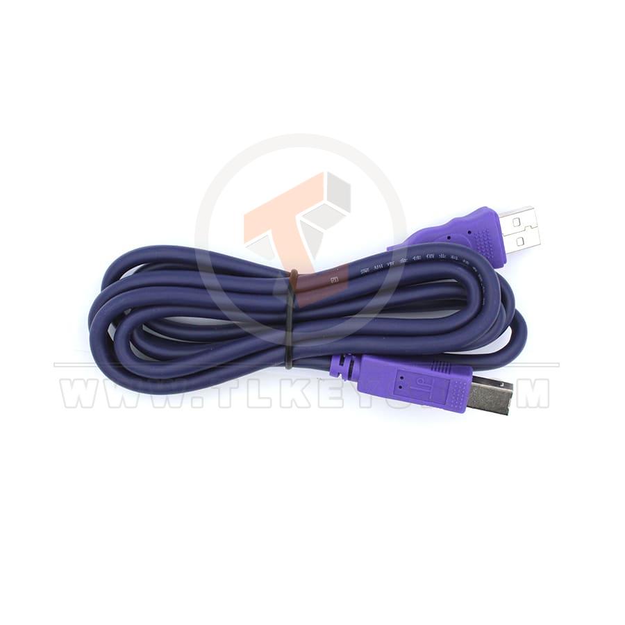
3. USB cable
4. NEC1 Adapter
5. NEC2 Adapter
6. NEC Adapter base PCB
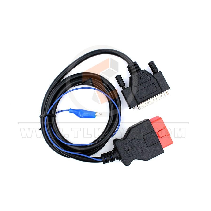
7. KLine in OBD line
8. OBD line
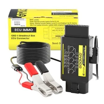
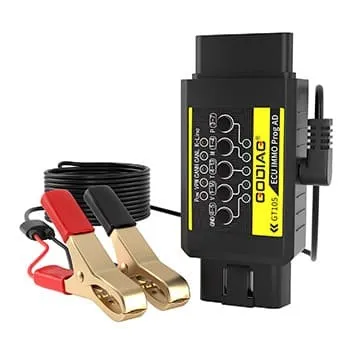
Mercedes Benz Connection Diagram Gearbox ECU ELV ISM by VVDI MB
The connection diagram illustrates the interconnection of various components in Mercedes-Benz vehicles such as the Electronic Control Unit (ECU), Electronic Steering Lock (ELV), Integrated Signal Module (ISM), and Gearbox using the VVDI MB device.It depicts how these parts are linked, their electronic interactions, and the necessary wiring and communications for proper functioning.
This diagram can be invaluable to technicians and engineers involved in repairing and maintaining Mercedes-Benz cars, providing them with a comprehensive guide to the electronic connections of the mentioned components.
With VVDI MB, technicians can perform a variety of operations such as key programming, electronic system repairs, diagnostic troubleshooting, etc., which require a deep understanding of how devices and units are interconnected within the vehicle.
These images and diagrams can be important in learning and understanding the maintenance and repair processes for these complex electronic systems in Mercedes-Benz vehicles.
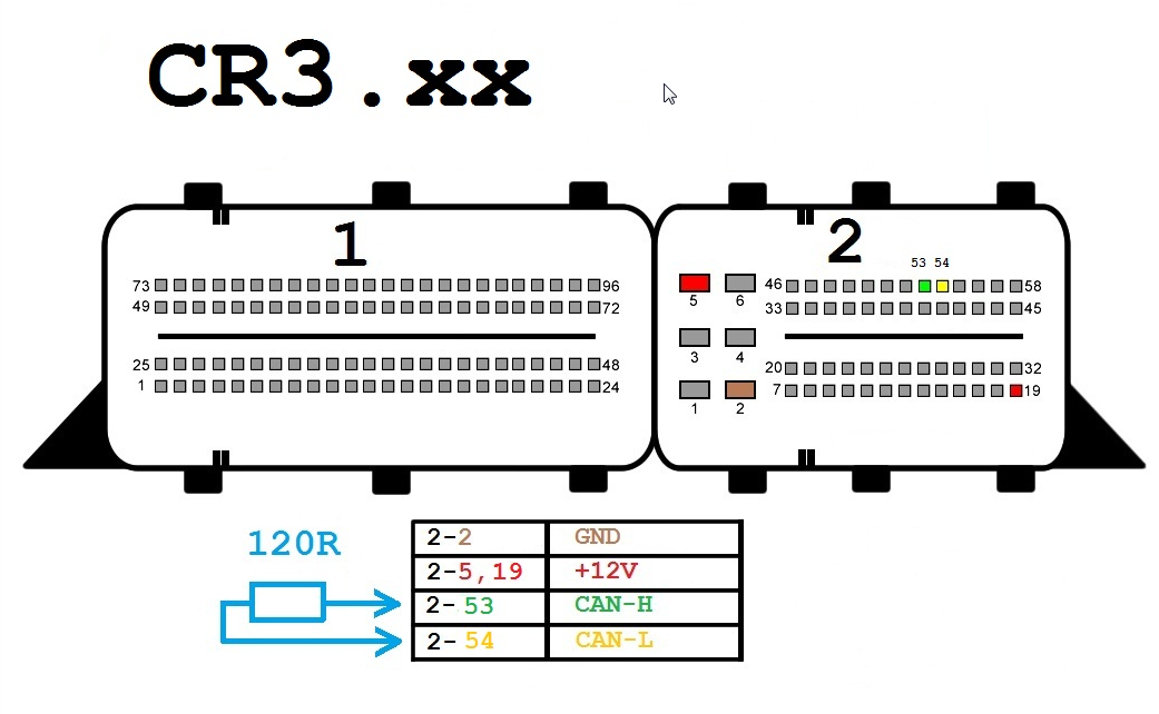
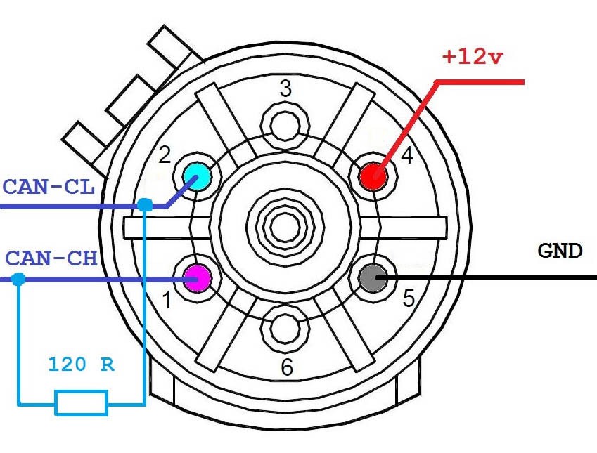
Connection Diagram ECU by VVDI MB
CR3-xx
Scheme components:
1: Power connector (12V)
2: CAN-CL line (green color)
3: CAN-CH line (yellow color)
4: Ground connector (GND)
5: K-line (purple color)
6: 120 ohm resistors (optional)
Basic ingredients:
Xhorse VVDI MB BGA Tool CR3.xx: Advanced programming tool to work on Mercedes Benz cars.
Engine Control Unit (ECU): An electronic control unit that operates a car's engine.
OBD-II Connector: A standard connector found on all OBD-II vehicles.
Cables: Special connection cables that connect the tool to the ECU.
Jobs:
Read PIN code:
VVDI MB BGA Tool CR3.xx allows you to read the PIN code of your vehicle's engine control unit (ECU) by connecting it to the OBD-II connector.
This PIN is used to program new keys to the vehicle.
Key programming:
VVDI MB BGA Tool CR3.xx allows you to program new keys for a vehicle using the PIN code or files taken from an existing key.
Various types of switches can be programmed, including BGA and NEC switches.
Other functions:
VVDI MB BGA Tool CR3.xx also supports other functions such as ECU reset, EIS, and ESL repair.
Delivery steps:
Connect the power connector (12V) to a suitable power outlet in the vehicle.
Connect the CAN-CL line (green color) to the CAN-CL connector on the ECU.
Connect the CAN-CH line (yellow color) to the CAN-CH connector on the ECU.
Connect the ground (GND) connector to any metal surface in the vehicle.
Connect the K-line (purple color) to the K-line connector on the ECU (optional).
Install 120 ohm resistors (optional) on the CAN-CL and CAN-CH lines.
Important notes:
Make sure to use the correct connectors and wires of the appropriate size.
Make sure all wires are connected securely before using the VVDI MB BGA Tool CR3.xx.
If you are not sure how to connect the VVDI MB BGA Tool CR3.xx, consult a professional technician.
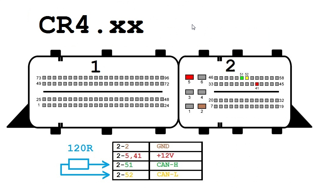
CR4-xx
Components:
- OBD-II Connector
- Xhorse VVDI MB BGA Tool CR4.xx
- 12 Volt Connector (Optional)
- 120 Ohm Resistors (Optional)
Wires:
- CAN-H (Yellow)
- CAN-L (Green)
- K-Line (Purple)
- GND (Black)
- +12V (Red)
Connection Steps:
- Connect the OBD-II connector to the VVDI MB BGA Tool CR4.xx.
- Connect the CAN-H wire to pin 6 on the OBD-II connector.
- Connect the CAN-L wire to pin 14 on the OBD-II connector.
- Connect the K-Line wire to pin 5 on the OBD-II connector.
- Connect the GND wire to pin 4 on the OBD-II connector.
- (Optional) Connect the +12V wire to pin 16 on the OBD-II connector.
- (Optional) Connect 120 Ohm resistors between the CAN-H and CAN-L wires.
Notes:
- Ensure all wires are correctly connected before using the VVDI MB BGA Tool CR4.xx.
- Connection steps may vary slightly depending on the specific car model and year of manufacture.
- Refer to the user manual of the VVDI MB BGA Tool CR4.xx for further detailed instructions.
Additional Information:
The VVDI MB BGA Tool CR4.xx can be used to perform various functions on Mercedes-Benz cars, including:
- Reading and removing PIN codes.
- Programming new keys for the car.
- Diagnosing ECU problems.
- Performing other maintenance and repair operations.
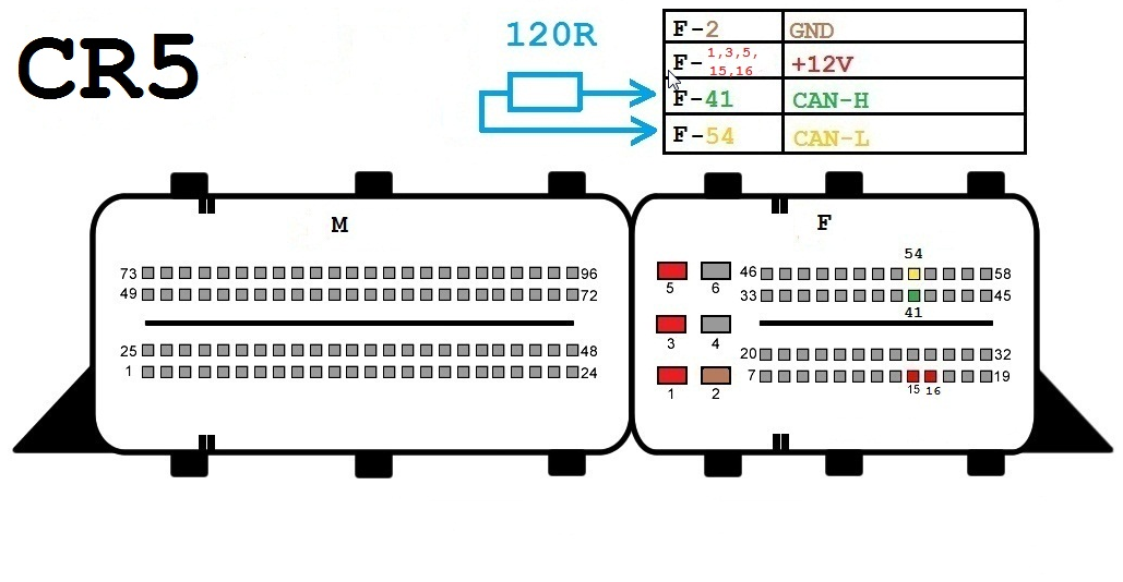
CR5
Components:
- OBD-II connector
- Xhorse VVDI MB BGA Tool CR5
- 12-volt connector (optional)
- 120-ohm resistors (optional)
Wires:
- CAN-H (Yellow)
- CAN-L (Green)
- K-Line (Purple)
- GND (Black)
- +12V (Red)
Connection Steps:
- Connect the OBD-II connector to the VVDI MB BGA Tool CR5.
- Connect the CAN-H wire to PIN 96 on the OBD-II connector.
- Connect the CAN-L wire to PIN 53 on the OBD-II connector.
- Connect the K-Line wire to PIN 54 on the OBD-II connector.
- Connect the GND wire to PIN 58 on the OBD-II connector.
- (Optional) Connect the +12V wire to pin number 45 on the OBD-II connector.
- (Optional) Connect the 120-ohm resistors between the CAN-H and CAN-L wires.
Notes:
- Ensure all wires are correctly connected before using the VVDI MB BGA Tool CR5.
- Connection steps may vary slightly depending on the car model and manufacturing year.
- Refer to the user manual of the VVDI MB BGA Tool CR5 for further detailed instructions.
Additional Information:
The VVDI MB BGA Tool CR5 can be used to perform various functions on Mercedes-Benz cars, including:
- Reading and removing PIN codes.
- Programming new keys for the car.
- Diagnosing ECU issues.
- Performing other maintenance and repair operations.
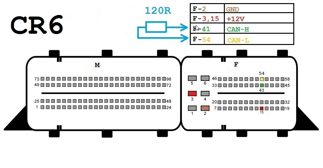
CR6
Components:
- OBD-II Connector
- Xhorse VVDI MB BGA Tool CR6
- 12V Connector (optional)
- 120-ohm Resistors (optional)
Wires:
- CAN-H (Yellow)
- CAN-L (Green)
- K-Line (Purple)
- GND (Black)
- +12V (Red)
Connection Steps:
- Connect the OBD-II connector to the VVDI MB BGA Tool CR6.
- Connect the CAN-H wire to pin 6 on the OBD-II connector.
- Connect the CAN-L wire to pin 14 on the OBD-II connector.
- Connect the K-Line wire to pin 5 on the OBD-II connector.
- Connect the GND wire to pin 4 on the OBD-II connector.
- (Optional) Connect the +12V wire to pin 16 on the OBD-II connector.
- (Optional) Connect the 120-ohm resistors between the CAN-H and CAN-L lines.
Notes:
- Ensure all wires are connected properly before using the VVDI MB BGA Tool CR6.
- Connection steps may vary slightly depending on the specific car model and year of manufacture.
- Please refer to the user manual of the VVDI MB BGA Tool CR6 for further detailed instructions.
Additional Information:
The VVDI MB BGA Tool CR6 can be used to perform various functions on Mercedes-Benz cars, including:
- Reading and removing PIN codes.
- Programming new keys for the car.
- Diagnosing ECU problems.
- Performing other maintenance and repair operations.
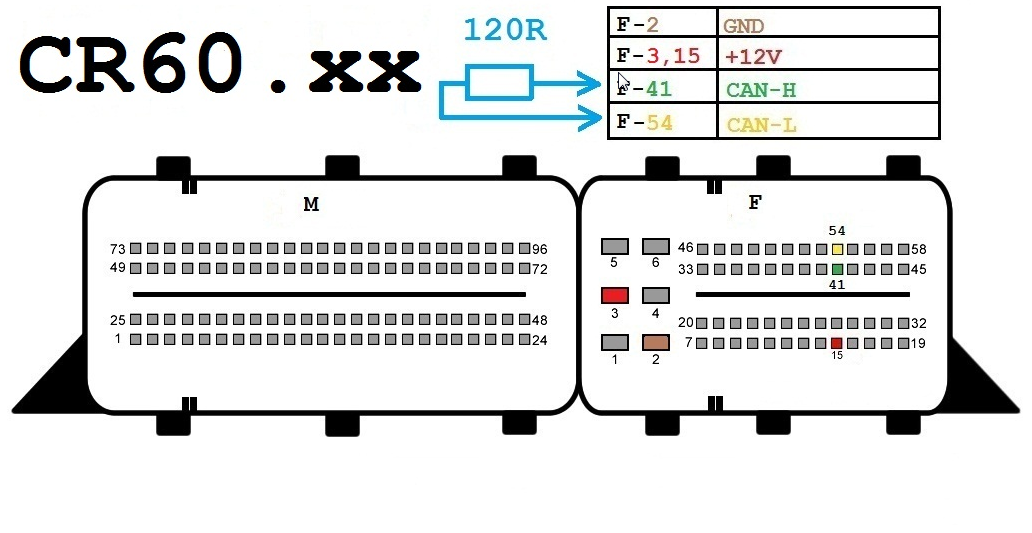
CR60-xx
Components:
- OBD-II Connector
- Xhorse VVDI MB BGA Tool CR60-xx
- 12 Volt Connector (Optional)
- 120-ohm Resistors (Optional)
Wires:
- CAN-H (Yellow)
- CAN-L (Green)
- K-Line (Purple)
- GND (Black)
- +12V (Red)
Connection Steps:
- Connect the OBD-II Connector to the VVDI MB BGA Tool CR60-xx.
- Connect the CAN-H wire to pin 6 on the OBD-II Connector.
- Connect the CAN-L wire to pin 14 on the OBD-II Connector.
- Connect the K-Line wire to pin 5 on the OBD-II Connector.
- Connect the GND wire to pin 4 on the OBD-II Connector.
- (Optional) Connect the +12V wire to pin 16 on the OBD-II Connector.
- (Optional) Connect 120-ohm resistors between the CAN-H and CAN-L wires.
Important Notes:
- Ensure all wires are properly connected before using the VVDI MB BGA Tool CR60-xx.
- Connection steps may vary slightly depending on the car model and manufacturing year.
- Refer to the user manual of the VVDI MB BGA Tool CR60-xx for further detailed instructions.
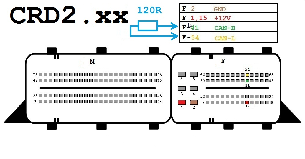
CRD2-xx
Components:
- OBD-II connector
- Xhorse VVDI MB BGA Tool CRD2-xx
- 12-volt connector (optional)
- 120-ohm resistors (optional)
Wiring:
- CAN-H (Yellow)
- CAN-L (Green)
- K-Line (Purple)
- GND (Black)
- +12V (Red)
Connection Steps:
- Connect the OBD-II connector to the VVDI MB BGA Tool CRD2-xx.
- Connect the CAN-H wire to pin 96 on the OBD-II connector.
- Connect the CAN-L wire to pin 53 on the OBD-II connector.
- Connect the K-Line wire to pin 54 on the OBD-II connector.
- Connect the GND wire to pin 58 on the OBD-II connector.
- (Optional) Connect the +12V wire to pin 45 on the OBD-II connector.
- (Optional) Connect 120-ohm resistors between the CAN-H and CAN-L lines.
Notes:
- Ensure all wires are connected correctly before using the VVDI MB BGA Tool CRD2-xx.
- Connection steps may vary slightly depending on the specific car model and year of manufacture.
- Refer to the user manual of the VVDI MB BGA Tool CRD2-xx for more detailed instructions.
Additional Information:
The VVDI MB BGA Tool CRD2-xx can be used to perform various functions on Mercedes-Benz cars, including:
- Reading and removing PIN codes.
- Programming new keys for the car.
- Diagnosing ECU issues.
- Performing other maintenance and repair operations.
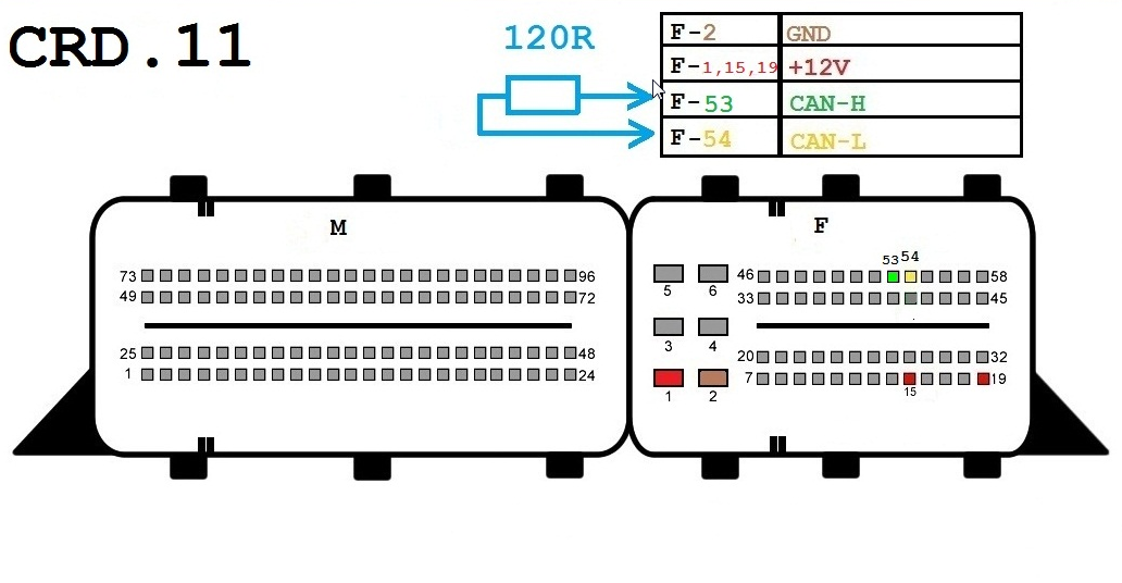
CRD-11
Components:
- OBD-II Connector
- Xhorse VVDI MB BGA Tool CRD-11
- 12V Connector (Optional)
- 120-ohm Resistors (Optional)
Wires:
- CAN-H (Yellow)
- CAN-L (Green)
- K-Line (Purple)
- GND (Black)
- +12V (Red)
Connection Steps:
- Connect the OBD-II Connector to the VVDI MB BGA Tool CRD-11.
- Connect the CAN-H wire to Pin 6 on the OBD-II Connector.
- Connect the CAN-L wire to Pin 14 on the OBD-II Connector.
- Connect the K-Line wire to Pin 5 on the OBD-II Connector.
- Connect the GND wire to Pin 4 on the OBD-II Connector.
- (Optional) Connect the +12V wire to Pin 16 on the OBD-II Connector.
- (Optional) Connect 120-ohm Resistors between CAN-H and CAN-L lines.
Notes:
- Ensure all wires are connected properly before using the VVDI MB BGA Tool CRD-11.
- Connection steps may vary slightly depending on the specific car model and manufacturing year.
- Refer to the user manual of the VVDI MB BGA Tool CRD-11 for further detailed instructions.
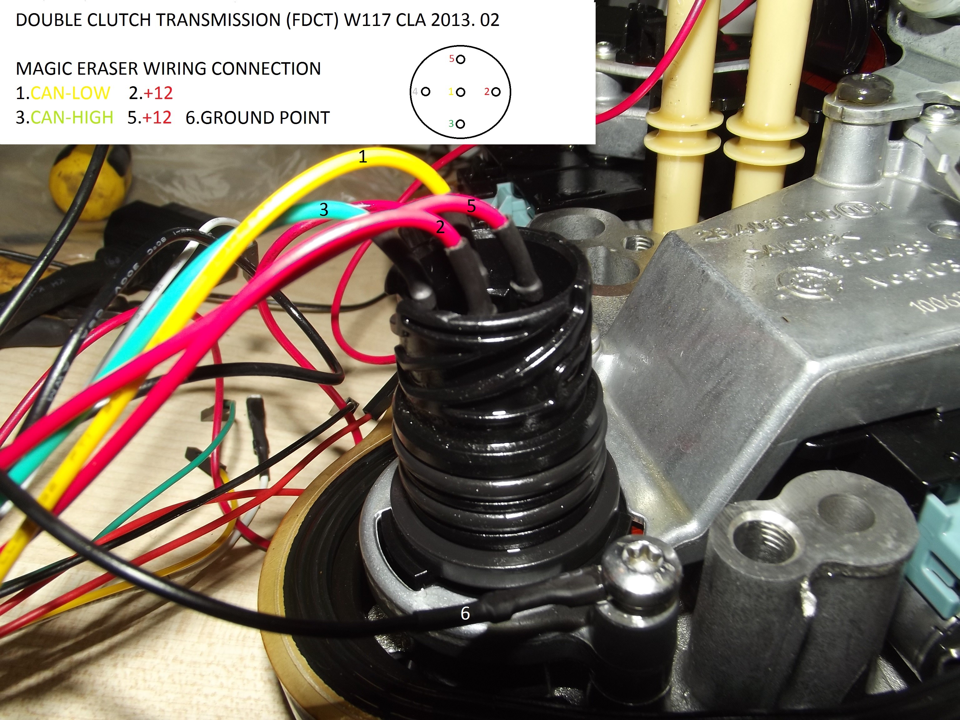
FDCT
Components:
- OBD-II connector
- Xhorse VVDI MB BGA Tool FDCT
- 12-volt connector (optional)
- 120-ohm resistors (optional)
Wires:
- CAN-H (yellow)
- CAN-L (green)
- K-Line (purple)
- GND (black)
- +12V (red)
Connection Steps:
- Connect the OBD-II connector to the VVDI MB BGA Tool FDCT.
- Connect the CAN-H wire to pin 6 on the OBD-II connector.
- Connect the CAN-L wire to pin 14 on the OBD-II connector.
- Connect the K-Line wire to pin 5 on the OBD-II connector.
- Connect the GND wire to pin 4 on the OBD-II connector.
- (Optional) Connect the +12V wire to pin 16 on the OBD-II connector.
- (Optional) Connect 120-ohm resistors between the CAN-H and CAN-L lines.
Notes:
- Ensure all wires are properly connected before using the VVDI MB BGA Tool FDCT.
- Connection steps may vary slightly depending on the specific car model and year of manufacture.
- Please refer to the user manual of the VVDI MB BGA Tool FDCT for further detailed instructions.
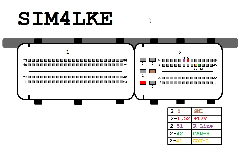
SIM4LKE
Components:
- OBD-II connector
- Xhorse VVDI MB BGA Tool SIM4LKE
- 12-volt connector (optional)
- 120-ohm resistors (optional)
Wires:
- CAN-H (Yellow)
- CAN-L (Green)
- K-Line (Purple)
- GND (Black)
- +12V (Red)
Connection Steps:
- Connect the OBD-II connector to the VVDI MB BGA Tool SIM4LKE.
- Connect the CAN-H wire to pin number 96 on the OBD-II connector.
- Connect the CAN-L wire to pin number 53 on the OBD-II connector.
- Connect the K-Line wire to pin number 54 on the OBD-II connector.
- Connect the GND wire to pin number 58 on the OBD-II connector.
- (Optional) Connect the +12V wire to pin number 45 on the OBD-II connector.
- (Optional) Connect the 120-ohm resistors between the CAN-H and CAN-L lines.
Important Notes:
- Ensure all wires are correctly connected before using the VVDI MB BGA Tool SIM4LKE.
- Connection steps may vary slightly depending on the specific car model and manufacturing year.
- Please refer to the user manual of the VVDI MB BGA Tool SIM4LKE for further detailed instructions.
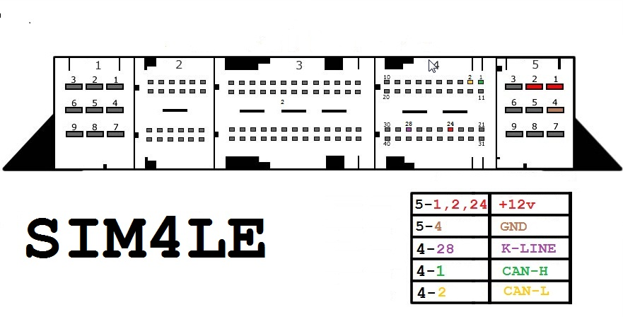
SIM4LE
Components:
- OBD-II connector
- Xhorse VVDI MB BGA Tool SIM4LE
- 12-volt connector (optional)
- 120-ohm resistors (optional)
Wires:
- CAN-H (Yellow)
- CAN-L (Green)
- K-Line (Purple)
- GND (Black)
- +12V (Red)
Connection Steps:
- Connect the OBD-II connector to the VVDI MB BGA Tool SIM4LE.
- Connect the CAN-H wire to pin 1 on the OBD-II connector.
- Connect the CAN-L wire to pin 2 on the OBD-II connector.
- Connect the K-Line wire to pin 24 on the OBD-II connector.
- Connect the GND wire to pin 5 on the OBD-II connector.
- (Optional) Connect the +12V wire to pin 28 on the OBD-II connector.
- (Optional) Connect 120-ohm resistors between the CAN-H and CAN-L lines.
Notes:
- Ensure all wires are correctly connected before using the VVDI MB BGA Tool SIM4LE.
- Connection steps may vary slightly depending on the specific car model and manufacturing year.
- Refer to the user manual of the VVDI MB BGA Tool SIM4LE for further detailed instructions.
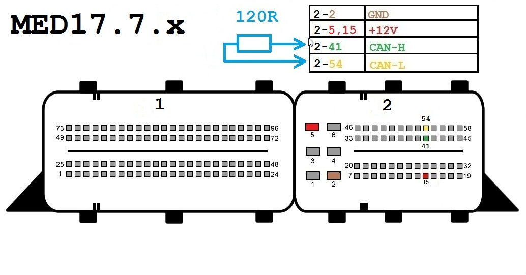
MED17-7-x
Components:
- OBD-II Connector
- Xhorse VVDI MB BGA Tool MED17-7-x
- 12-Volt Connector (Optional)
- 120-ohm Resistors (Optional)
Wiring:
- CAN-H (Yellow)
- CAN-L (Green)
- K-Line (Purple)
- GND (Black)
- +12V (Red)
Connection Steps:
- Connect the OBD-II Connector to the VVDI MB BGA Tool MED17-7-x.
- Connect the CAN-H wire to Pin 6 on the OBD-II Connector.
- Connect the CAN-L wire to Pin 14 on the OBD-II Connector.
- Connect the K-Line wire to Pin 5 on the OBD-II Connector.
- Connect the GND wire to Pin 4 on the OBD-II Connector.
- (Optional) Connect the +12V wire to Pin 16 on the OBD-II Connector.
- (Optional) Connect 120-ohm Resistors between the CAN-H and CAN-L lines.
Notes:
- Ensure all wires are properly connected before using the VVDI MB BGA Tool MED17-7-x.
- Connection steps may vary slightly depending on the specific car model and manufacturing year.
- Please refer to the user manual of the VVDI MB BGA Tool MED17-7-x for further detailed instructions.
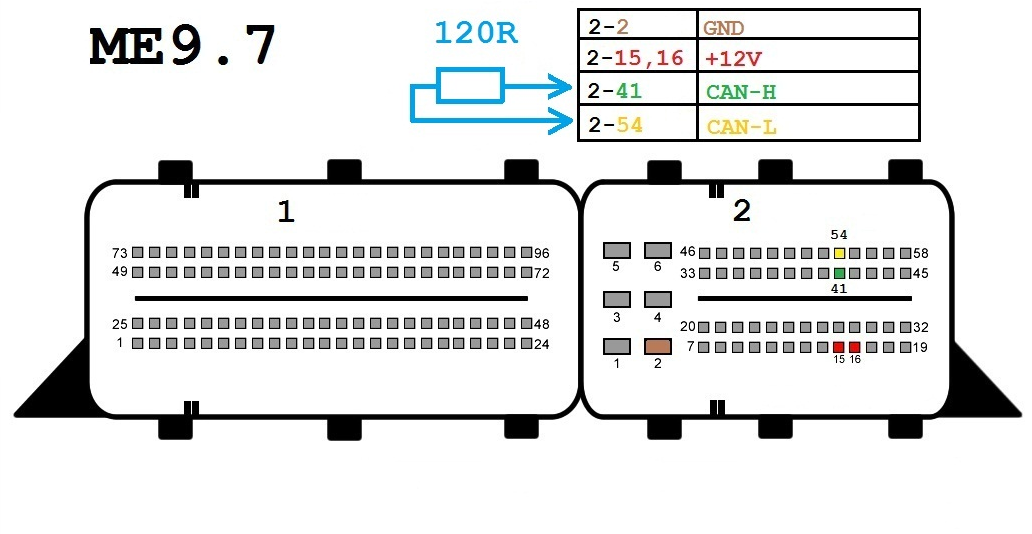
ME9-7
Components:
- OBD-II connector
- Xhorse VVDI MB BGA Tool ME9-7
- 12-volt connector (optional)
- 120-ohm resistors (optional)
Wires:
- CAN-H (Yellow)
- CAN-L (Green)
- K-Line (Purple)
- GND (Black)
- +12V (Red)
Connection Steps:
- Connect the OBD-II connector to the VVDI MB BGA Tool ME9-7.
- Connect the CAN-H wire to pin 6 on the OBD-II connector.
- Connect the CAN-L wire to pin 14 on the OBD-II connector.
- Connect the K-Line wire to pin 5 on the OBD-II connector.
- Connect the GND wire to pin 4 on the OBD-II connector.
- (Optional) Connect the +12V wire to pin 16 on the OBD-II connector.
- (Optional) Connect 120-ohm resistors between the CAN-H and CAN-L lines.
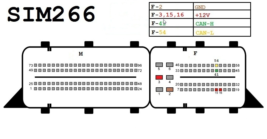
SIM266
Components:
- OBD-II connector
- Xhorse VVDI MB BGA Tool ME9-7
- 12-volt connector (optional)
- 120-ohm resistors (optional)
Wires:
- CAN-H (Yellow)
- CAN-L (Green)
- K-Line (Purple)
- GND (Black)
- +12V (Red)
Connection Steps:
- Connect the OBD-II connector to the Xhorse VVDI MB BGA Tool ME9-7.
- Connect the CAN-H wire to pin number 6 on the OBD-II connector.
- Connect the CAN-L wire to pin number 14 on the OBD-II connector.
- Connect the K-Line wire to pin number 5 on the OBD-II connector.
- Connect the GND wire to pin number 4 on the OBD-II connector.
- (Optional) Connect the +12V wire to pin number 16 on the OBD-II connector.
- (Optional) Connect 120-ohm resistors between the CAN-H and CAN-L lines.
Important Notes:
- Ensure all wires are correctly connected before using the Xhorse VVDI MB BGA Tool ME9-7.
- Connection steps may vary slightly depending on the specific car model and year of manufacture.
- Refer to the user manual of the Xhorse VVDI MB BGA Tool ME9-7 for further detailed instructions.
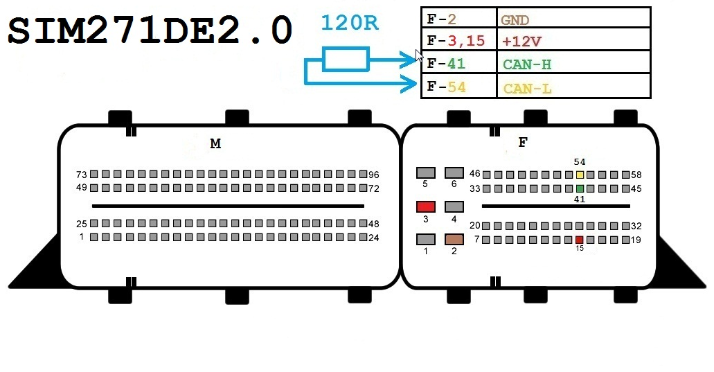
SIM271DE2-0
Components:
- OBD-II connector
- Xhorse VVDI MB BGA Tool SIM271DE2-0
- 12-volt connector (optional)
- 120-ohm resistors (optional)
Wiring:
- CAN-H (Yellow)
- CAN-L (Green)
- K-Line (Purple)
- GND (Black)
- +12V (Red)
Connection Steps:
- Connect the OBD-II connector to the VVDI MB BGA Tool SIM271DE2-0.
- Connect the CAN-H wire to pin number 41 on the OBD-II connector.
- Connect the CAN-L wire to pin number 54 on the OBD-II connector.
- Connect the K-Line wire to pin number 72 on the OBD-II connector.
- Connect the GND wire to pin number 1 on the OBD-II connector.
- (Optional) Connect the +12V wire to pin number 24 on the OBD-II connector.
- (Optional) Connect 120-ohm resistors between the CAN-H and CAN-L lines.
Notes:
- Ensure all wires are correctly connected before using the VVDI MB BGA Tool SIM271DE2-0.
- Connection steps may vary slightly depending on the specific car model and year of manufacture.
- Please refer to the user manual of the VVDI MB BGA Tool SIM271DE2-0 for further detailed instructions.
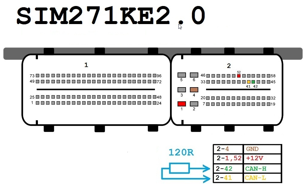
SIM271KE2-0
Components:
- OBD-II connector
- Xhorse VVDI MB BGA Tool SIM271KE2-0
- 12-volt connector (optional)
- 120-ohm resistors (optional)
Wires:
- CAN-H (Yellow)
- CAN-L (Green)
- K-Line (Purple)
- GND (Black)
- +12V (Red)
Connection Steps:
- Connect the OBD-II connector to the Xhorse VVDI MB BGA Tool SIM271KE2-0.
- Connect the CAN-H wire to pin 41 on the OBD-II connector.
- Connect the CAN-L wire to pin 54 on the OBD-II connector.
- Connect the K-Line wire to pin 72 on the OBD-II connector.
- Connect the GND wire to pin 1 on the OBD-II connector.
- (Optional) Connect the +12V wire to pin 24 on the OBD-II connector.
- (Optional) Connect the 120-ohm resistors between the CAN-H and CAN-L lines.
Notes:
- Ensure all wires are correctly connected before using the Xhorse VVDI MB BGA Tool SIM271KE2-0.
- Connection steps may vary slightly depending on the specific car model and year of manufacture.
- Please refer to the user manual of the Xhorse VVDI MB BGA Tool SIM271KE2-0 for further detailed instructions.
Gearbox
Components:
- Special connector for gearbox
- Xhorse VVDI MB BGA Tool
Wires:
- +12 volts (Red)
- GND (Black)
- K-Line (Purple, optional)
Connection Steps:
- Identify the location of the gearbox connector in your car. Refer to the car's user manual or online sources for assistance in identifying its location.
- Connect the special connector for the gearbox to the Xhorse VVDI MB BGA Tool.
- Connect the +12 volts wire to the red terminal on the gearbox connector.
- Connect the GND wire to the black terminal on the gearbox connector.
- (Optional) Connect the K-Line wire to the purple terminal on the gearbox connector. K-Line may not be required depending on the car or procedure being performed.
ISM
Components
- Special connector for ISM unit
- Xhorse VVDI MB BGA Tool
- 12-volt DC power source (optional)
- 120-ohm resistors (optional)
Wires
- CAN-H (Yellow)
- CAN-L (Green)
- +12 Volts (Red)
- GND (Black)
Connection Steps
- Locate the ISM unit connector in your car. Refer to the car's user manual or online sources for assistance in locating it.
- Connect the ISM unit connector to the Xhorse VVDI MB BGA Tool.
- Connect the CAN-H wire to the yellow terminal on the ISM unit connector.
- Connect the CAN-L wire to the green terminal on the ISM unit connector.
- (Optional) Connect the +12 Volts wire to the red terminal on the ISM unit connector.
- Connect the GND wire to the black terminal on the ISM unit connector.
- (Optional) Connect 120-ohm resistors between the CAN-H and CAN-L lines if your power source does not already provide termination resistance.
Steering Lock ELV W204
Components
- Special connector for ISM unit
- Xhorse VVDI MB BGA Tool
- 12-volt DC power source (optional)
- 120-ohm resistors (optional)
Wires
- CAN-H (Yellow)
- CAN-L (Green)
- +12V (Red)
- GND (Black)
Connection Steps
- Identify the location of the ISM unit connector in your car. Refer to the car's user manual or online sources to assist in locating it.
- Connect the ISM unit connector to the Xhorse VVDI MB BGA Tool.
- Connect the CAN-H wire to the yellow terminal on the ISM unit connector.
- Connect the CAN-L wire to the green terminal on the ISM unit connector.
- (Optional) Connect the +12V wire to the red terminal on the ISM unit connector.
- Connect the GND wire to the black terminal on the ISM unit connector.
- (Optional) Connect 120-ohm resistors between the CAN-H and CAN-L lines if your power source does not already provide resistor termination.
Be the first to review: “Xhorse VVDI MB BGA Tool Mercedes Benz Key Programmer Plus 1 Year Free Token”
Send Message
contact us
Address :Sharjah - Industrial No. 5, behind Maliah Road., shop No. 8, Property of Ali Nasir Mohamed Suleiman
Related Products

SKU:TL40328
$139.00
Page 1 of 2